Solidworks Counterbore Slot Rotate

- Solidworks Counterbore Slot Rotate Rows
- Solidworks Counterbore Slot Rotate Software
- Solidworks Counterbore Slot Rotate Blocks


Solidworks Counterbore Slot Rotate Rows
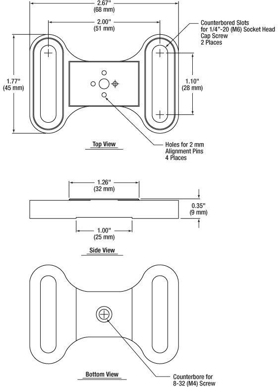
Counterbore: Countersink: Hole: Straight Tap: Tapered Tap: Legacy Hole: Holes created before the SOLIDWORKS 2000 release. Counterbore Slot: Specifies slot holes of length Slot Length. Countersink Slot: Slot: Standard: Specifies the hole standard. For example, select ANSI Metric or JIS. Type: Specifies drill sizes, tap drills, dowel holes. Mar 01, 2013 The slot then advances.225' along the bore axis while sweeping to 22.5 degrees. It then moves an additional.15' straight along the bore axis. The purpose of the slot is to rotate the bolt 22.5 degrees to engage the locking lugs. Any help is greatly appreciated! Edit: Figured it out! Here is a picture of the slot in an AR15 bolt carrier. We received a support call from a customer the other day and they were trying to create an angled slot on a cylinder in SOLIDWORKS.There is a catch, they need to create the slot so that the edges of the slot, are perpendicular to the inside and outside diameter of the cylinder. The Slot command accelerates the development of curvilinear geometry. This online video demonstrates how to quickly define parameters within an object by working with slots in SolidWorks. You will learn how to use various slot tools including the Center Point Arc Slot to easily rotate objects and create angled slots, which saves you time by reducing the need to individually draw lines. SOLIDWORKS 2014 now allows for an automated way to create Hole Wizard Slots. Using the Hole Wizard feature there are three new slots available: Slot, Counter.
Solidworks Counterbore Slot Rotate Software
A drilling machine is used for this operation, and a typical counterboring tool is shown in Fig. 14.26. The operation involves enlarging existing holes, and the depth of the enlarged hole is controlled by a stop on the drilling machine. The location of the counterbored hole is assisted by a pilot at the tip of the tool which is a clearance fit in the previously drilled hole. A typical use for a counterbored hole is to provide a recess for the head of a screw, as shown in Fig. 14.27 or a flat surface for an exposed nut or bolt, as in Fig. 14.28. The flat surface in Fig. 14.28 could also be obtained by spotfacing.

Figure 14.29 shows methods of dimensioning counterbores. Note that, in every case, it is necessary to specify the size of counterbore required. It is not sufficient to state 'COUNTERBORE FOR M10 RD HD SCREW', since obviously the head of the screw will fit into any counterbore which is larger than the head.
Solidworks Counterbore Slot Rotate Blocks
Was this article helpful?